
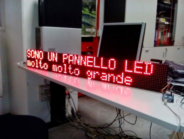
I have been asked by my company to create a system for production monitoring.
A very important component of this system will be a large LED panel showing production status.
Unfortunately I discoverd such components (for example the excellent Alphabrite panels) are very expensive: the mean quotation for a 2 line-21 chars ethernet controllable display is around 3000 USD!.
So I tought i could save several thousands euros of my budget with a little DIY.
I discovered there are a lot of “nearly standard” and nearly-inexpensive LED panels that can be cascaded in order to assemble a large display.
I focused my attention on a 32×16 with pitch (pixel distance) of 10mm designed for outdoor (extrabright).
This kind of product is avaliable from several sellers on the Hong-Kong market (aliexpress) for about 9 USD.
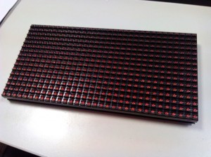
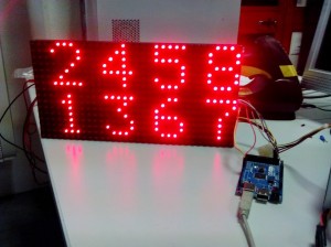
I thougt I could cascade 4 of them in order to get a panel 960mm X 320mm (really wide…) that should be visible up to 30m.
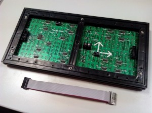
Unfortunately this module is based on a undocumented protocol (hub08 – hub12). But since it is a very stupid device, with a little of reverse-engineering it is possible to understand how to drive every single pixel.
The core of the device is composed by a certain amount of 74HC595 cascaded one each other.
This component is a serial (SPI) 8 bit shift-register. Cascading them the display can load info on pixel status (on/off) and send pin output to drive LEDs.
The bad new is there is not 1 register (byte) every 8 LEDs but the system is “interlaced” with a certain scan ratio.
My panel, like the vaste majority of outdoor devices, has a 1/4 scan ratio. This means only 1 line over 4 is displayed at each scan time.
A full display refresh needs 4 scans.
In a 1/16 scan display a single line is displayed and the device needs 16 scans for a full refresh
If you are not sure about the scan ratio of your display you can simply count the amount of 74HC595 soldered on the back side and:
scan-ratio = pixWidth x pixHeight / 8 / number_of_HC595.
The lines to be displayed at scan time are selected through a 74HC138 line decoder. In this design, for 1/4 scan, only 2 input are used to select scan line and the third (pin 3) is grounded since not needed (2 bits -> 4 lines)
Lines are driven through 4 double mosfets, but pay attention: I cannot see any load resistor connected to the LEDs on the backside. So, I suggest to PWM the “enable output” pin to be sure not to damage your panel.
The overflow pin of the last serial register is connected to the output connector.
Connecting it to the input of another panel you can cascade them and enlarge your display.
Connections
The main power supply connector is in the middle. You can power your panels with a standard PC PSU.
Be careful if you don’t connect power supply the panel will try to drain power from your Arduino (risk to damage it!) trough signal and enable pins.
On the board there are 2 DMD connectors: 1 is for input 1 for output (in order to cascade other devices.)
The standard DMD pinout is:
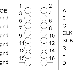
On a 1/4 SCAN only A and B pins are used for data.
OE is output enable and you have to PWM it as explained above.
CLK SCK and R are to be connected to your Arduino SPI pins (may vary with Arduino version)
Software
After 1 hour testing I discovered 8 pixel blocks composing the full scan line are loaded with a certain order:
So the first scan line you will upload via SPI will be composed by total of 8 bytes.
They will match the following sequence: first line of char 1 – first line of char 2…..
Code examples
The first is a very simple sketch. It will show some chars on your single LED panel.
(code is ugly, but kept as simple as possible : ))
The second is more complex. Itcomposed by two files: main code and font definition (font.h).
It handles cascaded panels and allow to send the string to be displayed through the serial monitor.
In order to handle continuous refresh even it implements a sort of multitasking. So the TimerOne library is required.
/**************************************************************

*

*  Sample sketch for driving 32x16 LED PANEL (1/4 scan) with

*  HUB12 protocol

*

*************************************************************/
#include
//Pins specific for Mega .See Arduino SPI for a different board.
#define A 22
#define B 24
#define OE 26
#define R1 51
#define CLK 52
#define STB 53
//row to be shown (1-4 since it is 1/4 scan)
byte row=0;
//brightness: increase->more bright
int br=500;
//some digits from a 8x8 font (numeric 1-8)
byte digits[]={
0x04, //1
0x0C,
0x04,
0x04,
0x04,
0x04,
0x0E,
0x00,
0x0E, //2
0x11,
0x01,
0x02,
0x04,
0x08,
0x1F,
0x00,
0x1F, //3
0x02,
0x04,
0x02,
0x01,
0x11,
0x0E,
0x00,
0x02, //4
0x06,
0x0A,
0x12,
0x1F,
0x02,
0x02,
0x00,
0x1F, //5
0x10,
0x1E,
0x01,
0x01,
0x11,
0x0E,
0x00,
0x06, //6
0x08,
0x10,
0x1E,
0x11,
0x11,
0x0E,
0x00,
0x1F,//7
0x01,
0x02,
0x04,
0x04,
0x04,
0x04,
0x00,
0x0E,//8
0x11,
0x11,
0x0E,
0x11,
0x11,
0x0E,
0x00,
};
void setup () {
pinMode(A, OUTPUT);
pinMode(B, OUTPUT);
pinMode(OE, OUTPUT);
pinMode(R1, OUTPUT);
pinMode(CLK, OUTPUT);
pinMode(STB, OUTPUT);
SPI.begin();
delay(300);
}
//display alternatively scan lines
void loop(){
showRow(0);
showRow(1);
showRow(2);
showRow(3);
}
//Load and show row (1-4) i.e. 1 and 5, 2 and 6.....
void showRow(int row){
SPI.transfer(~(digits[row+36])); //5
SPI.transfer(~(digits[row+32]));
SPI.transfer(~(digits[row+4])); //1
SPI.transfer(~(digits[row]));
SPI.transfer(~(digits[row+44])); //6
SPI.transfer(~(digits[row+40]));
SPI.transfer(~(digits[row+12])); //2
SPI.transfer(~(digits[row+8]));
SPI.transfer(~(digits[row+52])); //7
SPI.transfer(~(digits[row+48]));
SPI.transfer(~(digits[row+20])); //3
SPI.transfer(~(digits[row+16]));
SPI.transfer(~(digits[row+60])); //8
SPI.transfer(~(digits[row+56]));
SPI.transfer(~(digits[row+28])); //4
SPI.transfer(~(digits[row+24]));
digitalWrite(STB,LOW);
digitalWrite(STB,HIGH);
scanrow(row);//enable encoder for the line loaded
//PWM like. Change br to adjust brightnes
digitalWrite(OE,HIGH);
delayMicroseconds(br);
digitalWrite(OE,LOW);
delayMicroseconds(900);
}
//enable encoder for this row in order to show it
void scanrow(int r){
if(r==0){
digitalWrite(A,0);
digitalWrite(B,0);
}
else if(r==1){
digitalWrite(A,1);
digitalWrite(B,0);
}
else if(r==2){
digitalWrite(A,0);
digitalWrite(B,1);
}
else if(r==3){
digitalWrite(A,1);
digitalWrite(B,1);
}
}
Second example: driving interactively an arbitrary number of cascaded panels
/**************************************************************

*

*  Sample sketch for driving 24x16 LED PANEL (1/4 scan) with

*  HUB12 protocol

*  Support for multiple cascaded panels

*  Get text TO DISPLAY from the serial monitor

*

*************************************************************/
#include
#include
#include "font.h"
Timer t;
Timer t1;
//Pins specific for Mega.See Arduino SPI for a different board.
#define A 2
#define B 3
#define OE 4
#define R1 51
#define CLK 52
#define STB 53
//number of cascaded panels
#define N_PANELS 4
//row to be shown (1-4 since it is 1/4 scan)
byte row=0;
//brightness: increase->more bright
int br=400;
int incomingByte = 0;
//buffer 8 characters for N_PANELS
byte stringDisp[8*N_PANELS]={
'a','b','c','d','e','f','g','h','i','j','k','l','m','n','o','p','q','r','s','t','u','v','x','y','0','1','2','3','4','5','6','7',
};
//pixBuffer reserved space for N_PANELS
//contains status of every single pixel in our display!
byte pixBuffer[8*8*N_PANELS]={
};
void setup () {
Serial.begin(9600);
pinMode(A, OUTPUT);
pinMode(B, OUTPUT);
pinMode(OE, OUTPUT);
pinMode(R1, OUTPUT);
pinMode(CLK, OUTPUT);
pinMode(STB, OUTPUT);
SPI.begin();
//set timers
//first timer is the refresh rate for the 1/4 scan
t.every(6,display);
//second timer is for change display text IF INPUT AVAILABLE
t1.every(1000,checkInput);
delay(300);
}
void loop(){
t.update();
t1.update();
}
//diplay alternatively the 4 scan lines
void display(){
showRow(0);
showRow(1);
showRow(2);
showRow(3);
}
//Load and show row (1-4) i.e. 1-5-9-13, 2-6-10-14.....
void showRow(int row){
int col=0;//is a column of 2 chars
for(col=0;col<4*N_PANELS;col++){//show 2 characters every cicle
SPI.transfer(~(pixBuffer[row+(col*8)+4+(32*N_PANELS)]));
SPI.transfer(~(pixBuffer[row+(col*8)+(32*N_PANELS)]));
SPI.transfer(~(pixBuffer[row+(col*8)+4]));
SPI.transfer(~(pixBuffer[row+(col*8)]));
}
digitalWrite(STB,LOW);
digitalWrite(STB,HIGH);
scanrow(row);//enable encoder for the line loaded
//PWM like. Change br to adjust brightnes
digitalWrite(OE,HIGH);
delayMicroseconds(br);//PWM per aggiustare luminosità
digitalWrite(OE,LOW);
delayMicroseconds(900);
}
//enable encoder for this row in order to show it
void scanrow(int r){
if(r==0){
digitalWrite(A,0);
digitalWrite(B,0);
}
else if(r==1){
digitalWrite(A,1);
digitalWrite(B,0);
}
else if(r==2){
digitalWrite(A,0);
digitalWrite(B,1);
}
else if(r==3){
digitalWrite(A,1);
digitalWrite(B,1);
}
}
//check if input from the serial monitor is available
//and update the display
void checkInput(void){
int x=0;
int y=0;
if(Serial.available()){
int h;
//clean display
for(h=0;h<(8*N_PANELS);h++)stringDisp[h]=32;
}
while (Serial.available() > 0) {
// read the incoming byte:
incomingByte = Serial.read();//only UP to the efective string length
if(x<(8*N_PANELS)) stringDisp[x]=incomingByte;
x++;
}
loadBuffer();
}
//load buffer with character pixels of the string
//performing a lookup on the FONT table
void loadBuffer(void){
int x;
int y;
for(y=0;y<(8*(N_PANELS));y++){
for(x=0;x<8;x++){
pixBuffer[x+8*y]=font[8*stringDisp[y]+x-(31*8)];//char under <=31 not defined
}
}
}
FONT DEFINITION: font.h
/**********************************************

*

*        USED FONTS DEFINITIONS

*

**********************************************/
byte font[]={
//SPACE
0x00,
0x00,
0x00,
0x00,
0x00,
0x00,
0x00,
0x00,
// !
//SPACE
0x00,
0x00,
0x00,
0x00,
0x00,
0x00,
0x00,
0x00,
// !
0x04,
0x04,
0x04,
0x04,
0x00,
0x00,
0x04,
0x00,
// "
0x0A,
0x0A,
0x0A,
0x00,
0x00,
0x00,
0x00,
0x00,
// #
0x0A,
0x0A,
0x1F,
0x0A,
0x1F,
0x0A,
0x0A,
0x00,
// $
0x04,
0x0F,
0x14,
0x0E,
0x05,
0x1E,
0x04,
0x00,
// %
0x18,
0x19,
0x02,
0x04,
0x08,
0x13,
0x03,
0x00,
// &
0x0C,
0x12,
0x14,
0x08,
0x15,
0x12,
0x0D,
0x00,
// '
0x0C,
0x04,
0x08,
0x00,
0x00,
0x00,
0x00,
0x00,
// (
0x02,
0x04,
0x08,
0x08,
0x08,
0x04,
0x02,
0x00,
// )
0x08,
0x04,
0x02,
0x02,
0x02,
0x04,
0x08,
0x00,
// *
0x00,
0x04,
0x15,
0x0E,
0x15,
0x04,
0x00,
0x00,
// +
0x00,
0x04,
0x04,
0x1F,
0x04,
0x04,
0x00,
0x00,
// ,
0x00,
0x00,
0x00,
0x00,
0x0C,
0x04,
0x08,
0x00,
// -
0x00,
0x00,
0x00,
0x1F,
0x00,
0x00,
0x00,
0x00,
// .
0x00,
0x00,
0x00,
0x00,
0x00,
0x0C,
0x0C,
0x00,
// /
0x00,
0x01,
0x02,
0x04,
0x08,
0x10,
0x00,
0x00,
// 0
0x0E,
0x11,
0x13,
0x15,
0x19,
0x11,
0x0E,
0x00,
// 1
0x04,
0x0C,
0x04,
0x04,
0x04,
0x04,
0x0E,
0x00,
// 2
0x0E,
0x11,
0x01,
0x02,
0x04,
0x08,
0x1F,
0x00,
// 3
0x1F,
0x02,
0x04,
0x02,
0x01,
0x11,
0x0E,
0x00,
// 4
0x02,
0x06,
0x0A,
0x12,
0x1F,
0x02,
0x02,
0x00,
// 5
0x1F,
0x10,
0x1E,
0x01,
0x01,
0x11,
0x0E,
0x00,
// 6
0x06,
0x08,
0x10,
0x1E,
0x11,
0x11,
0x0E,
0x00,
// 7
0x1F,
0x01,
0x02,
0x04,
0x04,
0x04,
0x04,
0x00,
// 8
0x1E,
0x11,
0x11,
0x0E,
0x11,
0x11,
0x0E,
0x00,
// 9
0x0E,
0x11,
0x11,
0x0F,
0x01,
0x02,
0x0C,
0x00,
// :
0x00,
0x0C,
0x0C,
0x00,
0x0C,
0x0C,
0x00,
0x00,
// ;
0x00,
0x0C,
0x0C,
0x00,
0x0C,
0x04,
0x08,
0x00,
// <
0x02,
0x04,
0x08,
0x10,
0x08,
0x04,
0x02,
0x00,
// =
0x00,
0x00,
0x1F,
0x00,
0x1F,
0x00,
0x00,
0x00,
// >
0x08,
0x04,
0x02,
0x01,
0x02,
0x04,
0x08,
0x00,
// ?
0x0E,
0x11,
0x01,
0x02,
0x04,
0x00,
0x04,
0x00,
// @
0x0E,
0x11,
0x01,
0x0D,
0x15,
0x15,
0x0E,
0x00,
// A
0x0E,
0x11,
0x11,
0x11,
0x1F,
0x11,
0x11,
0x00,
// B
0x1E,
0x09,
0x09,
0x0E,
0x09,
0x09,
0x1E,
0x00,
// C
0x0E,
0x11,
0x10,
0x10,
0x10,
0x11,
0x0E,
0x00,
// D
0x1E,
0x09,
0x09,
0x09,
0x09,
0x09,
0x1E,
0x00,
// E
0x1F,
0x10,
0x10,
0x1F,
0x10,
0x10,
0x1F,
0x00,
// F
0x1F,
0x10,
0x10,
0x1E,
0x10,
0x10,
0x10,
0x00,
// G
0x0E,
0x11,
0x10,
0x13,
0x11,
0x11,
0x0F,
0x00,
// H
0x11,
0x11,
0x11,
0x1F,
0x11,
0x11,
0x11,
0x00,
// I
0x0E,
0x04,
0x04,
0x04,
0x04,
0x04,
0x0E,
0x00,
// J
0x07,
0x02,
0x02,
0x02,
0x02,
0x12,
0x0C,
0x00,
// K
0x11,
0x12,
0x14,
0x18,
0x14,
0x12,
0x11,
0x00,
// L
0x10,
0x10,
0x10,
0x10,
0x10,
0x10,
0x1F,
0x00,
// M
0x11,
0x1B,
0x15,
0x15,
0x11,
0x11,
0x11,
0x00,
// N
0x11,
0x19,
0x19,
0x15,
0x13,
0x13,
0x11,
0x00,
// O
0x0E,
0x11,
0x11,
0x11,
0x11,
0x11,
0x0E,
0x00,
// P
0x1E,
0x11,
0x11,
0x1E,
0x10,
0x10,
0x10,
0x00,
// Q
0x0E,
0x11,
0x11,
0x11,
0x15,
0x12,
0x1D,
0x00,
// R
0x1E,
0x11,
0x11,
0x1E,
0x14,
0x12,
0x11,
0x00,
// S
0x0E,
0x11,
0x10,
0x0E,
0x01,
0x11,
0x0E,
0x00,
// T
0x1F,
0x04,
0x04,
0x04,
0x04,
0x04,
0x04,
0x00,
// U
0x11,
0x11,
0x11,
0x11,
0x11,
0x11,
0x0E,
0x00,
// V
0x11,
0x11,
0x11,
0x11,
0x11,
0x0A,
0x04,
0x00,
// W
0x11,
0x11,
0x11,
0x15,
0x15,
0x1B,
0x11,
0x00,
// X
0x11,
0x11,
0x0A,
0x04,
0x0A,
0x11,
0x11,
0x00,
// Y
0x11,
0x11,
0x11,
0x0A,
0x04,
0x04,
0x04,
0x00,
// Z
0x1F,
0x01,
0x02,
0x04,
0x08,
0x10,
0x1F,
0x00,
// [
0x0E,
0x08,
0x08,
0x08,
0x08,
0x08,
0x0E,
0x00,
////////////
//0x00,
// \
0x00,
0x10,
0x08,
0x04,
0x02,
0x01,
0x00,
0x00,
// ]
0x0E,
0x02,
0x02,
0x02,
0x02,
0x02,
0x0E,
0x00,
// ^
0x04,
0x0A,
0x11,
0x00,
0x00,
0x00,
0x00,
0x00,
// _
0x00,
0x00,
0x00,
0x00,
0x00,
0x00,
0x1F,
0x00,
// `
0x10,
0x08,
0x04,
0x00,
0x00,
0x00,
0x00,
0x00,
// a
0x00,
0x00,
0x0E,
0x01,
0x0F,
0x11,
0x0F,
0x00,
// b
0x10,
0x10,
0x16,
0x19,
0x11,
0x11,
0x1E,
0x00,
// c
0x00,
0x00,
0x0E,
0x11,
0x10,
0x11,
0x0E,
0x00,
// d
0x01,
0x01,
0x0D,
0x13,
0x11,
0x11,
0x0F,
0x00,
// e
0x00,
0x00,
0x0E,
0x11,
0x1F,
0x10,
0x0E,
0x00,
// f
0x02,
0x05,
0x04,
0x0E,
0x04,
0x04,
0x04,
0x00,
// g
0x00,
0x00,
0x0D,
0x13,
0x13,
0x0D,
0x01,
0x0E,
// h
0x10,
0x10,
0x16,
0x19,
0x11,
0x11,
0x11,
0x00,
// i
0x04,
0x00,
0x0C,
0x04,
0x04,
0x04,
0x0E,
0x00,
// j
0x02,
0x00,
0x06,
0x02,
0x02,
0x12,
0x0C,
0x00,
// k
0x08,
0x08,
0x09,
0x0A,
0x0C,
0x0A,
0x09,
0x00,
// l
0x0C,
0x04,
0x04,
0x04,
0x04,
0x04,
0x0E,
0x00,
// m
0x00,
0x00,
0x1A,
0x15,
0x15,
0x15,
0x15,
0x00,
// n
0x00,
0x00,
0x16,
0x19,
0x11,
0x11,
0x11,
0x00,
// o
0x00,
0x00,
0x0E,
0x11,
0x11,
0x11,
0x0E,
0x00,
// p
0x00,
0x00,
0x16,
0x19,
0x19,
0x16,
0x10,
0x10,
// q
0x00,
0x00,
0x0D,
0x13,
0x13,
0x0D,
0x01,
0x01,
// r
0x00,
0x00,
0x16,
0x19,
0x10,
0x10,
0x10,
0x00,
// s
0x00,
0x00,
0x0F,
0x10,
0x1E,
0x01,
0x1F,
0x00,
// t
0x08,
0x08,
0x1C,
0x08,
0x08,
0x09,
0x06,
0x00,
// u
0x00,
0x00,
0x12,
0x12,
0x12,
0x12,
0x0D,
0x00,
// v
0x00,
0x00,
0x11,
0x11,
0x11,
0x0A,
0x04,
0x00,
// w
0x00,
0x00,
0x11,
0x11,
0x15,
0x15,
0x0A,
0x00,
// x
0x00,
0x00,
0x11,
0x0A,
0x04,
0x0A,
0x11,
0x00,
// y
0x00,
0x00,
0x11,
0x11,
0x13,
0x0D,
0x01,
0x0E,
// z
0x00,
0x00,
0x1F,
0x02,
0x04,
0x08,
0x1F,
0x00,
//
0x02,
0x04,
0x04,
0x08,
0x04,
0x04,
0x02,
0x00,
// |
0x04,
0x04,
0x04,
0x00,
0x04,
0x04,
0x04,
0x00,
//
0x08,
0x04,
0x04,
0x02,
0x04,
0x04,
0x08,
0x00,
// ~
0x00,
0x00,
0x08,
0x15,
0x02,
0x00,
0x00,
0x00,
// 5F
0x00,
0x00,
0x00,
0x00,
0x00,
0x00,
0x00,
0x00,
// 60
0x00,
0x00,
0x00,
0x00,
0x00,
0x00,
0x00,
0x00,
// 61
0x00,
0x00,
0x00,
0x00,
0x00,
0x00,
0x00,
0x00,
// 62
0x00,
0x00,
0x00,
0x00,
0x00,
0x00,
0x00,
0x00,
// 63
0x00,
0x00,
0x00,
0x00,
0x00,
0x00,
0x00,
0x00,
// 64
0x00,
0x00,
0x00,
0x00,
0x00,
0x00,
0x00,
0x00,
// 65
0x00,
0x00,
0x00,
0x00,
0x00,
0x00,
0x00,
0x00,
// 66
0x00,
0x00,
0x00,
0x00,
0x00,
0x00,
0x00,
0x00,
// 67
0x00,
0x00,
0x00,
0x00,
0x00,
0x00,
0x00,
0x00,
// 68
0x00,
0x00,
0x00,
0x00,
0x00,
0x00,
0x00,
0x00,
// 69
0x00,
0x00,
0x00,
0x00,
0x00,
0x00,
0x00,
0x00,
// 6A
0x00,
0x00,
0x00,
0x00,
0x00,
0x00,
0x00,
0x00,
// 6B
0x00,
0x00,
0x00,
0x00,
0x00,
0x00,
0x00,
0x00,
// 6C
0x00,
0x00,
0x00,
0x00,
0x00,
0x00,
0x00,
0x00,
// 6D
0x00,
0x00,
0x00,
0x00,
0x00,
0x00,
0x00,
0x00,
// 6E
0x00,
0x00,
0x00,
0x00,
0x00,
0x00,
0x00,
0x00,
// 6F
0x00,
0x00,
0x00,
0x00,
0x00,
0x00,
0x00,
0x00,
// 70
0x00,
0x00,
0x00,
0x00,
0x00,
0x00,
0x00,
0x00,
// 71
0x00,
0x00,
0x00,
0x00,
0x00,
0x00,
0x00,
0x00,
// 72
0x00,
0x00,
0x00,
0x00,
0x00,
0x00,
0x00,
0x00,
// 73
0x00,
0x00,
0x00,
0x00,
0x00,
0x00,
0x00,
0x00,
// 74
0x00,
0x00,
0x00,
0x00,
0x00,
0x00,
0x00,
0x00,
// 75
0x00,
0x00,
0x00,
0x00,
0x00,
0x00,
0x00,
0x00,
// 76
0x00,
0x00,
0x00,
0x00,
0x00,
0x00,
0x00,
0x00,
// 77
0x00,
0x00,
0x00,
0x00,
0x00,
0x00,
0x00,
0x00,
// 78
0x00,
0x00,
0x00,
0x00,
0x00,
0x00,
0x00,
0x00,
// 79
0x00,
0x00,
0x00,
0x00,
0x00,
0x00,
0x00,
0x00,
// 7A
0x00,
0x00,
0x00,
0x00,
0x00,
0x00,
0x00,
0x00,
// 7B
0x00,
0x00,
0x00,
0x00,
0x00,
0x00,
0x00,
0x00,
// 7C
0x00,
0x00,
0x00,
0x00,
0x00,
0x00,
0x00,
0x00,
// 7D
0x00,
0x00,
0x00,
0x00,
0x00,
0x00,
0x00,
0x00,
// 7E
0x00,
0x00,
0x00,
0x00,
0x00,
0x00,
0x00,
0x00,
// 7F
0x00,
0x00,
0x00,
0x00,
0x00,
0x00,
0x00,
0x00
};
Congratulations! A great job. Next step will be builduing a high level app to deal with Arduino easily.
Here you can have a look at our led sign. They use a different CPU but the operating principle is
almost the same.
Regards,
led sign
Hey! you’ve really made our jobs easier. Thanks so much. I too was looking for an idea to put up a price list board using LED lighting modules outside of my restaurant. Will seek help from an electrician and work it out with this blog. Thank you.
Hello
Congratulations for this work.
I want to upload these codes to ESP8266.
Can you send the code for 4 panels to my e-mail address?
If you want I can send you the ESP8266-P10 code when I run it.
I wish you a good day.
akekec@gmail.com
We have 3 panels (4 modules each) running in our factory.
The new WIFI version is based on ESP8266 (probably Wemos D1 mini clone).
I think the code is nearly the same: my coworkers translated and loaded in no time…